The Hauptwerk Virtual Pipe Organ Projects
OPUS II - A New Virtual Pipe Organ
(This site is hosted on the Raspberry Pi - a web server for £25.00
- and consuming only 5 watt!)
PLEASE NOTE: in 2021 the web
address of this site changes to:
my-music.kaspencer.com (NB.: no "www")
The old site-address (www.my-music.mywire.org) will cease to
exist during 2021!
| When you have finished this page, visit the OPUS I page: How it all started OPUS I - The first organ! |
| This page is all about OPUS II - my New Hauptwerk Project |
|
OPUS I was my first Hauptwerk Virtual Pipe Organ I built my first Hauptwerk Virtual Pipe Organ project in 2007-2008. It has lasted me for eleven years. During those years, it grew: it gained multiple channel audio, which gives it truly impressive sound which amazes everyone who hears and plays it. It also had three new PCs over those years, each with more powerful CPUs, more RAM and then increased fixed disc storage until it had 2 x 3TB in a RAID array and 32 Gigabyte of RAM. Then it gained a pair of Novation LaunchPads, which greatly increased the flexibility of control. However, OPUS I was always seen as a proof of concept, because it lacked the refined playing-aids that professional organists who visited and played the instruments expected. And so, over several years, a plan for the design and building of a major new instrument started to crystallise in my mind. OPUS II - A New Hauptwerk Virtual Pipe Organ is finished! After the experience of designing and building OPUS I, I decided to build a second console incorporating all the ideas which had built up in my mind with the first organ. As mentioned already, OPUS II has some of the playing aids that professional organists and recitalists who have played OPUS I have missed on the first organ. And as my ideas became firmer, I realised that I could make use of additional features to improve those areas which virtual organs have to control but which real pipe organs do not need. These include changing the stop names when each different organ is loaded, and providing controls for virtual organ facilities such as recording audio & MIDI. 1. OPUS II CONSOLE VIDEO TOURS There are now available a Video Tours of OPUS II. There are two parts, each of about 40 minutes. PART I: provides an introductory tour and explanation of the console, pedalboard, expression pedals and toe pistons; the keyboard stack and thumb pistons; the central control console, and finally the two stop jambs. You can watch PART I at: https://youtu.be/7vGIMomsehs PART II: shows an initial montage of photographs taken during many stages of construction. It goes on to show the internals of each section of the instrument: the central control console, the component shelf and stop jambs. We then switch on the organ and illustrate the use of the organ, combination set and temperament loading, the registration stepper and the audio and MIDI recording controls. You can watch PART II at: https://youtu.be/ENOmvTRibis If you enjoy the videos, do please subscribe and click on "like"! There are other videos featuring the organ: perform a Google search for kaspenceruk to find my YouTube channel. |
My new book: "All about Hauptwerk" is available now from:  If you buy at Lulu, contact us for a free PDF of the book A full explanation of how to setup and use Hauptwerk: keyboards/ pedalboard/ expression pedals/ and controller accessories. There are also design details showing how to make a pedalboard and console. Multi-channel audio setup, convolution reverb setup, tuning and temperament are also covered. There is a YouTube Video which shows what is in the book. |
||
|
2. OPUS II DEVELOPMENT 2.1 The Console First, we have a new console. I have improved the look of the new console by using clear varnish rather than dark stain. That makes it take on a more modern appearance. OPUS I was stained in Walnut, a choice which I regretted on completion, as I considered that the unstained natural wood, light in colour, had a better appearance. The console is also somewhat heavier, as the spruce/pine frame is constructed in thicker wood, and the panels are 9mm ply rather than 3.00-5.00mm. This makes the console more stable, and stronger. The platform/keyboard stack support is wider and more substantial. Unfortunately the decorated engraved and embossed mouldings which I used to such good effect (my mitreing of the mouldings has been often admired) are no longer available, and so a plain edging has been used along the platform. You may note that the inages shown here illustrate three stages in the design & development of the Central Control Console and of the Stop Jambs. In fact there were two other stages in the Stop Jamb design but they are not shown here. |
You will see as you read, that OPUS II features a
development not very often seen in self-built Hauptwerk organs: that of
Automatic Stop Labelling. This solves the issue of
attaching stop name labels onto your console every time you decide to play a
different sample set. This project provides instant labelling as soon as
the organ has loaded, and is exactly as shown in the images of
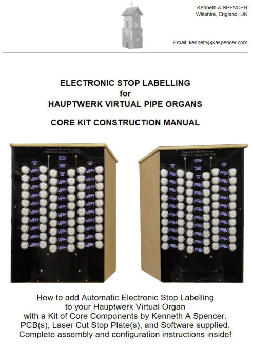
OPUS II on this page and elsewhere. A Core Component Kit is now available comprising: the kasLABS v3.2x software which drives the project; sets of up to six printed circuit boards (you can use fewer if you wish) and laser cut Stop Jamb Plates in black acrylic or high quality beech-finish ply. The Project Construction Manual is available now (the cover page is shown on the right). You can get it here. It describes everything in detail with lots of pictures and photographs. As well as the Core Components, you can purchase the other components from me, or source them yourself. Full costing details are included in the Construction Manual. If you doubt your ability to build it, I can build part or all of it for you. Send an email including your full postal address details, to the email address which you can see at the bottom of this page, and I'll let you have details of costs and options, as well as tell you how you can get the Project Booklet! Click on the link at the top of this panel to go to the Project Page for the Stop Jamb Labels, where you can read more details which will help you decide whether you can make use of this innovation for Hauptwerk self-build organ enthusiasts. The project page includes links to the five construction videos which I have placed on my YouTube channel. |
 |
|
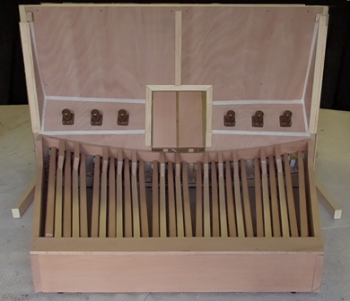
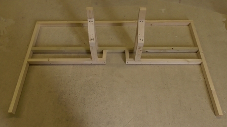 1. The console frame base |
 2. The console frame (The aperture is for expression pedals) |
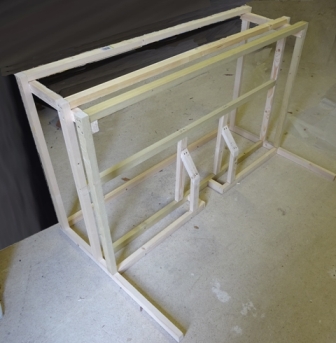
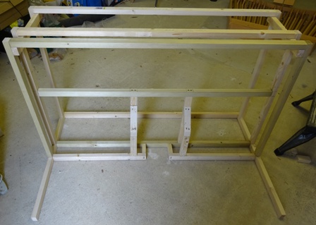 3. The console frame (front elevation) |
 4. The console frame and front panelling |
 6. The console almost complete, varnished, and with the keyboard platform fitted. |
 5. Console frame with mouldings and toe pistons |
|
These images show how a frame was constructed from spruce and pine,
beginning with the base. The front of the base has a battens of sufficient width to encompass the pedalboard. The frame is also equipped with a space which forms a niche for the two expression pedals, and a sloping panel on which toe pistons can be mounted. Decorative mouldings round off the construction and provide a neat edge surrounding the expression pedal aperture. |
||
2.2 The Pedalboard The pedalboard used in OPUS I was obtained from a deconsecrated Methodist Chapel in Loughborough, as you'll already know if you have read the account of OPUS I. It was about 110 years old, and was MIDIfied using reed switches and a 32-switch parallel MIDI Encoder from MIDI Gadget Boutique - see the OPUS I page for details. I decided that OPUS II would warrant a new pedalboard. After some investigation I opted to have the pedalboard constructed in Italy. It was quite an expensive exercise, but it was reasonably promptly executed. However, there was a failure to meet the full specification of the RCO pedalboard design, and its derivative AGO. Resolving that error would have required a return of some of the pedalboard parts - that is not convenient, and I am still thinking about that, but I may put the error right myself. Apart from that (quite significant issue) the pedalboard is very usable, and well made. It has slightly thicker pedal sticks than did my original OPUS I pedalboard, in line with modern practice. I do not like the short cables with which the pedalboard connects to its MIDI controller, and will alter that arrangement in due course to make it easier to connect, and also to see the LEDs that indicate the status of the controller during configuration. The pedalboard has two expression pedals of standard design, but using Hall Effect transistors and neodymium button magnets. These work very well, and have the advantage of stability, and simplicity compared with optical systems, and of being completely free from the effects of wear suffered by potentiometer systems. Above the pedalboard, I have mounted a set of six toe pistons, five with an LED active indicator, and a sixth as a pedal divisional cancel. |
||
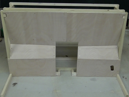
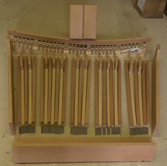 1. The pedalboard parts (unassembled) |
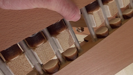 2. Pedalboard detail (Toe end: showing damping pads and springs) |
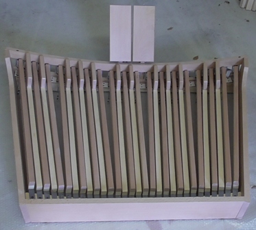 3. The pedalboard assembled |
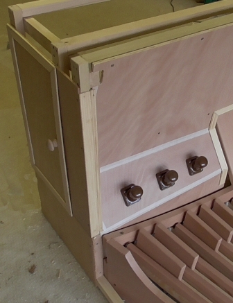 4. Left access door & part of pedalboard |
 . .6. The console, varnished, with the pedalboard in situ. |
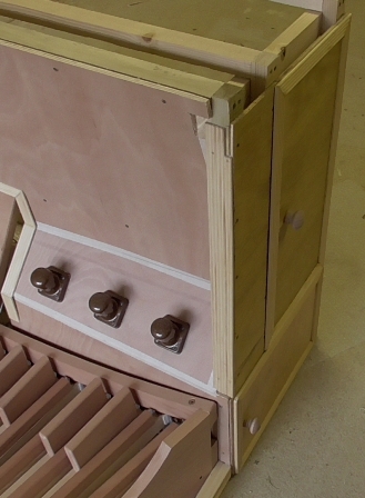 5. Right access doors & part of pedalboard |
|
These images show the pedalboard, how it is constructed, and
fitted into the console frame.. The front of the console base has a batten on each side of sufficient width to encompass the pedalboard. The two expression pedals mounted on the pedalboard frame fit into the niche, and six toe pistons are mounted on a sloping panel. Hinged doors one each side provide access to the computing and electronics of the organ. |
||
|
2.3 The Keyboard Stack I decided to make the keyboard stack a major feature of the new organ. Therefore, I specified a set of three brand new, especially built high quality keyboards in the "Baroque style" with tracker action, cherry naturals and ebony sharps & flats and beech key cheeks. The keys would get their feel from having a full length key-stick, enabling a traditional balance point to be used, rather than the very short keys associated more recently with many keyboards. In the event, the three-manual keyboard stack weighed in at 50kg! I was glad I didn't decide to have a four-manual stack. There would also be a full set of 37 divisional and general thumb pistons, using illuminated buttons. six of the thumb pistons would enable control of a fourth manual division, enabling the upper manual to function fully with a Swell and a Solo division in larger instruments. Unfortunately I failed to specify exactly how the thumb piston MIDI parameters for MIDI IN (senses the engagement of a thumb piston) and MIDI OUT (illuminates the selected LED) should be matched (i.e. same MIDI channel and Note ON) to ease Hauptwerk configuration. Release of the source code for the Arduino controller was refused, and the only correction option offered was a return of the Arduino PCB for reconfiguration. I did not regard this as satisfactory as it would mean dismantling on the keyboard to extract the controller. |
||
 1. The traditional keyboard bases (in workshop) |
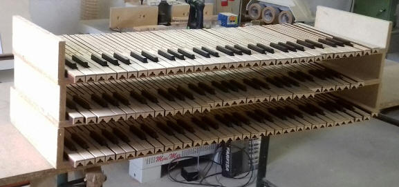 2. The baroque-style keys in construction (in workshop) 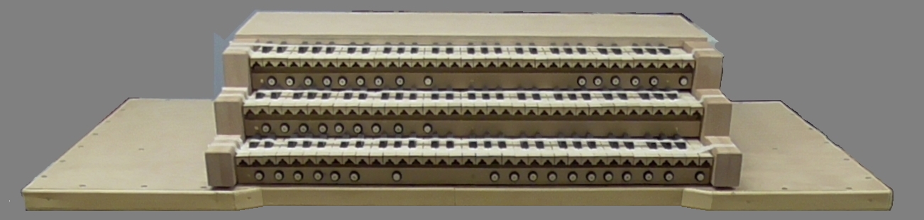 4. The keyboard stack mounted on its platform |
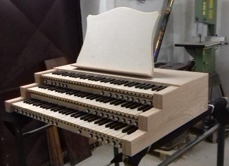 3. The keyboard stack (in workshop) The music desk shown was not actually used. |
| These images show the keyboard stack, it's features, and how it fitted onto the console keyboard platform. | ||
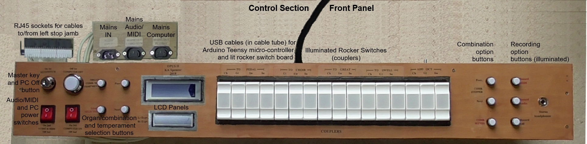
2.4 The Control Section I wanted to make the operation of this instrument as independent of the computer keyboard, mouse and monitor screen as possible. In fact, the keyboard, mouse and monitor are required only for logging into the PC and installing or configuring a sample set. The entire organ, including the computer can be turned on and off from the control section, and the 2x16 character LCD display shows loading status of the organ during loading, and the name of the currently loaded combination set. Recording of MIDI and Audio can be started (both simultaneously if required) and stopped using push buttons (on the right) and LEDs indicated when recording is taking place. There is also an illuminated combination setter switch on the right. An Arduino Teensy micro-controller is used to operate most of these control functions. I wrote the code in C, after reading an article by Tim Howard on his WordPress Blog. |
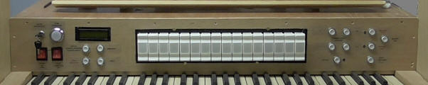 The Control Control console (Mk1) (Jan 2018) |
| This image shows the Mk1 Control Section. On the far left, there are power switches for the Audio & MIDI and for starting up the PC. A push button also enables the PC to be shut down from the console. Next is a 2-line LCD display which can show the currently loaded Organ, Combination Set and Temperament. Four Push button switches enable selection and loading of any installed Organ, Combination Set and Temperament. Centrally, the 16 lit rocker switches enable control of the couplers. On the right of the rocker switches, four push buttons enable sequenced selection of registrations, whilst a fifth button allows combination selection. On the far right, three push buttons allow MIDI and Audio recording to be switched on and off. The lower button on that group closes the Hauptwerk software. |
|
2.5 The Stop Jambs In Phase I of my OPUS I console organ stops were controlled by a touch screen. I found that the touch screen was a little subject to bounce, or would sometimes miss the touch. Subsequently, in Phase II of OPUS I I fitted two Novation LaunchPads for stop control (and for control of a number of other functions, including coupler control, MIDI and Audio recording, and PC shutdown). These were, and remain excellent. However, for OPUS II I decided to attempt to use a mechanism a little more like that used in most real pipe organs. Solenoid actuated moving stop jambs were discounted as they cost in the region of £40-44, and I decided to have 120 stops! After investigation I settled on illuminated push buttons, as commonly used in arcade machines. These have a micro-switch enclosed in a switch housing with an LED, and can be obtained at a very low-cost from several sources. The fact that they make an audible click on operation was not seen as a disadvantage, as electro-magnetic action draw stops also make quite a noise in action. There would be a left and right stop jamb, bearing 60 switches each. There would be a MIDI encoder and a MIDI decoder board in each stop jamb. |
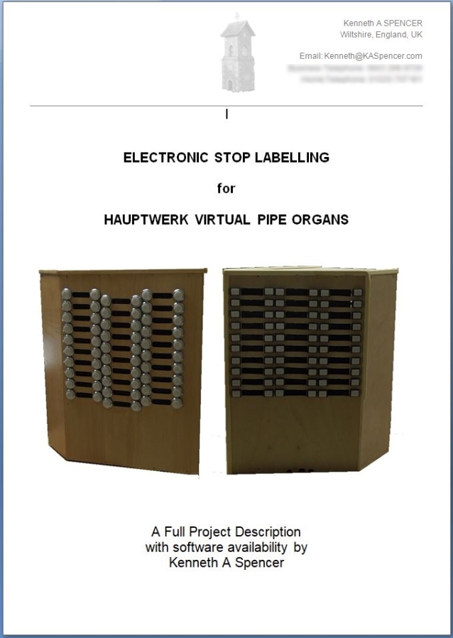
A Second Option Project for you On the right of this panel, you will see the Cover Page of the Project Booklet: "Electronic Stop Labels for Hauptwerk Virtual Pipe Organs". This booklet is now available from me (the email address is at the bottom of this page). It is available in print form only. The Project Booklet describes how to add electronic displays to your Hauptwerk organ using SSD1306 OLED devices. Full constructional diagrams and explanations are given. I have made available one version of my Electronic Labelling Software (known as kasLABS v1.4x) and the booklet explains fully how to use it. I can install the software on your own Arduino Dues, or I can supply Dues with the software already installed. An alternative version of the software which uses larger OLEDs with its own supporting Project Booklet is shown towards the top of this page. The second version of the stop jamb designs are as seen on the OPUS II YouTube Tour (see the kaspenceruk channel on YouTube) and on OPUS II images on this page. |
 |
|
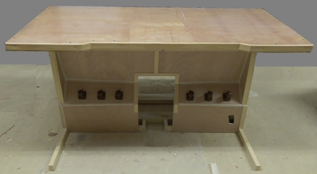
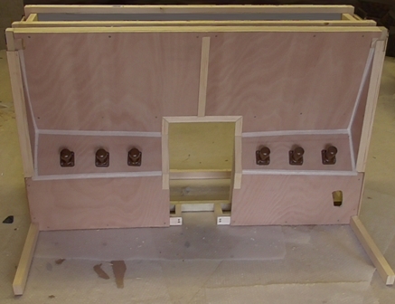
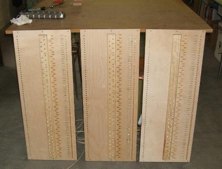
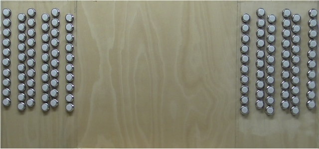 1. The uncut stop jamb panels (Mk I) with buttons fitted |
|||
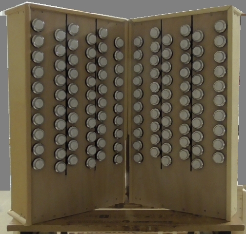 2. The stop jamb panels are cut and housed |
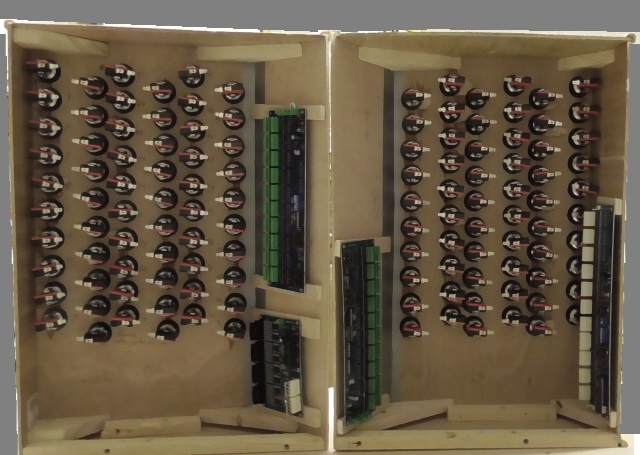 3. stop jambs ready for wiring |
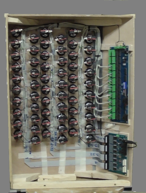 4. Right hand stop jamb wired |
|
| These images show the construction of the
first design version (Mk I) of the two stop jambs
in the initial design. There are 120 illuminated stop switches in six columns of twenty, vertically staggered. The space at the top of each jamb allows a label to be placed giving the organ name and builder. There is a space between each column for a vertical printed strip bearing the names of the stops to be inserted. (See below) |
|||
3. COMPLETING THE ORGAN 3.1 The Component Shelf A component shelf, accessible from behind the organ, supports the devices associated withy the organ. The apparent simplicity of the layout rather belies the complexity of the setup! |
|||
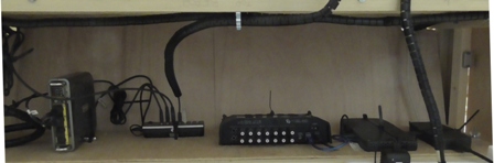 |
The device shelf carries the electronics and computing components. The components, from left to right, are: Far Left: MIDI Hub. Carries 4 MIDI-IN and 4 MIDI-OUT cables for the Pedalboard and Expression Pedals and for the Left and Right Stop Jambs Inner Left: 7-way USB Hub. Carries Keyboard Stack and Thumb Piston, Pedalboard Controller Power, Control Section (x2), Touchscreen and Hauptwerk dongle Centre: 16 channel USB Audio Device, Currently 3 Stereo Pairs, a Subwoofer and Stereo Headphone output occupy about half of the available channels Inner Right: PC Unit - Intel Skull Canyon. i7 CPU, 32GigaByte RAM, 2 Terabyte SSD disc Far Right: PC Power Supply |
||
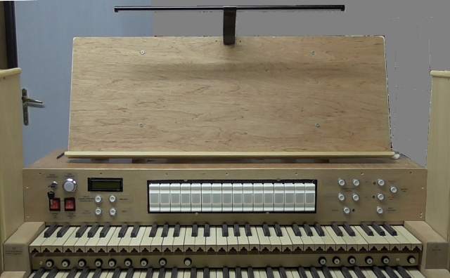
| 3.2 The Music Desk and Lamp A music desk and lamp sit on top of the control section, whilst the two stop jambs sit on either side of the keyboard stack, in a conventional layout. |
|||
 1. The MkI control section and music desk, with lamp (Jan 2018) |
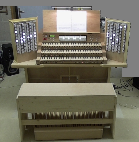 3. The Completed Console (MkI) (May 2018) |
 2. The control section with MkI stop jambs and MkI Stop Jambs in place. Stop Labels are on vertical strips between columns of stop switches. (May 2018) |
|
 4. The Central Control console (MkII) (December 2018) |
|||
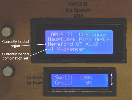 5. The Display Panels on MkII Control showing Expression Pedals and Organ Information |
6. The completed Console with MkII Stop Jambs and MkII Central Control Section (December 2018) |
 7. The completed console with MkV (final) Stop Jambs and MkII Central Control Section (October 2020) |
|
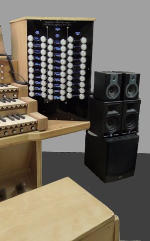 8. Far left: The right stop jamb in position |
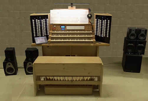
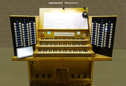 9. Above: The completed organ with MkV electronic stop labels and MkIII control console in place. |
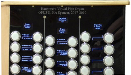 10. Above: A closer view of the Right Stop Jamb. The Hereford 67 organ is loaded. |
|
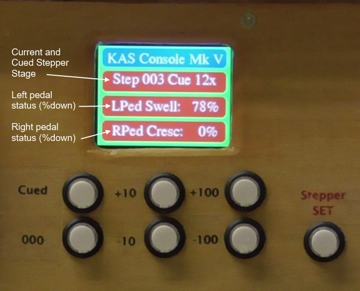 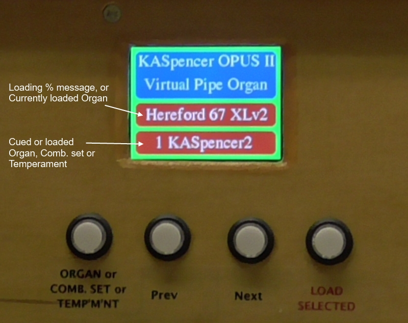 The left image shows the left TFT display and Organ/Combination Set and Temperament loading controls. The right image shows the right TFT, and the registration stepper controls. |
|||
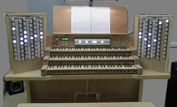
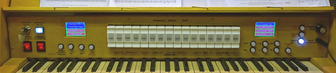 Above: 11. The MkIII (final) Central Control console. (October 2020) |
|||
4. COMPLETION The organ is now finished, and complete. Note in particular: the fully electronic Stop Labels designed and constructed during September 2019-February 2020. These load the Organ Location, Builder & Date, and all division and stop names (up to 120 stops and other controls) automatically as soon as an organ sample set finishes loading and is ready to play. Note also the Control Console, with two Full colour TFT display panels added, showing the Organ name/current Combination Set etc, the Cued and Current Registration Stepper Stage, as well the Expression pedal positions. |
|||
| Back to the Welcome page | Visit the Real Organ page | Visit the My Guitars page | |
| To the OPUS I Organ Project page | Back to the Virtual Organ page | Visit the Fenlanderz page | |
| Contact: my_music.site@kaspencer.com | |||
(c) KA Spencer 2020 |
|||